
Internal corner radius can affect machining cost because it limits the size of the cutter that can reach the corner.
A smaller radius usually needs a smaller cutter. Small cutters are less rigid, especially when they must reach deep into a pocket. This can make machining slower and more difficult. The manufacturer may also need extra finishing passes or additional tools to clear the corner.
However, a small radius does not automatically make a part expensive.
The real cost impact depends on the pocket depth, material, cutter size, tool reach, tolerance, and machining method.
An internal corner radius is the rounded corner where two vertical walls meet inside a pocket or cavity.
For example:
A smaller radius creates a sharper internal corner.
This article focuses on the radius between two vertical walls. It does not refer to the radius between a pocket wall and the pocket floor.
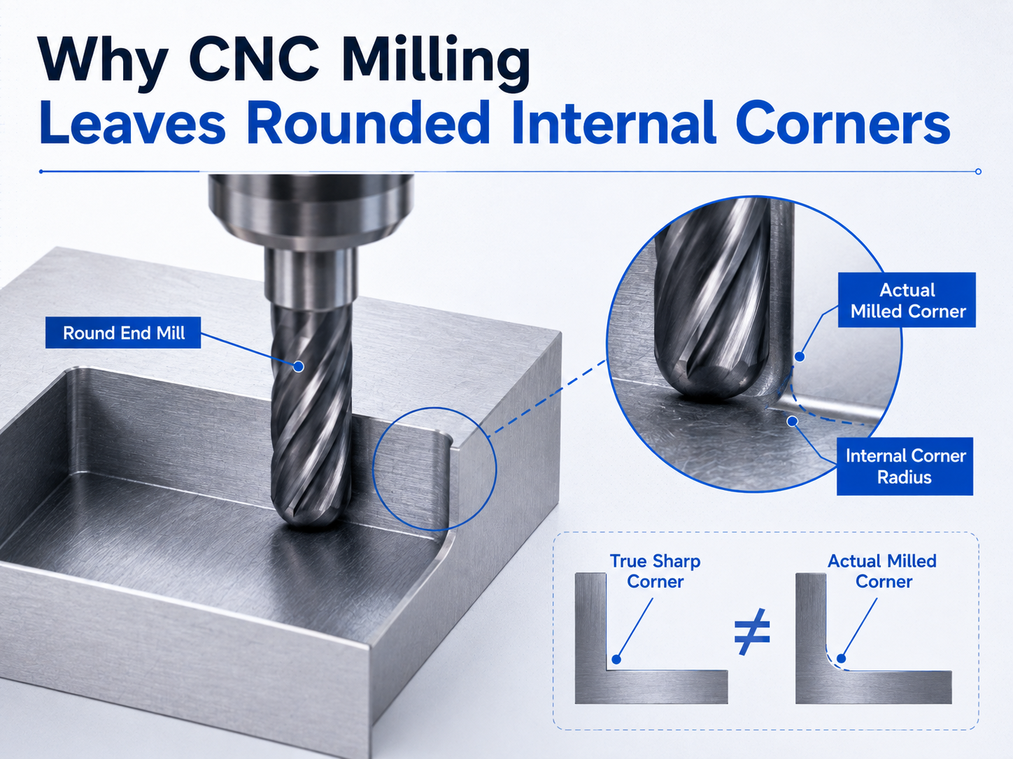
A standard CNC end mill is round.
When the cutter moves along two walls inside a pocket, its round shape naturally leaves a radius in the corner.
For example, a 6 mm end mill has a cutter radius of 3 mm.
The cutter cannot reach the exact zero-radius point of a sharp 90-degree internal corner.
This is a geometric limitation of normal milling. It is not caused by poor machine accuracy.
If a design requires a very sharp internal corner, another machining method or a design change may be needed.
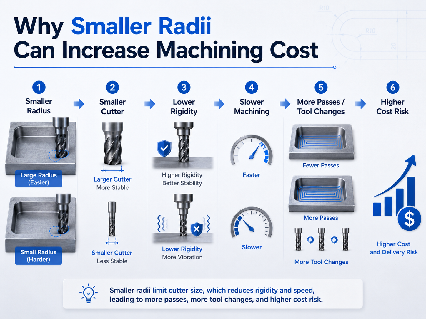
The basic relationship is simple:
Smaller radius → smaller cutter → lower rigidity → slower or more careful machining → more passes or extra tools → longer cycle time → potentially higher cost
This is not a fixed rule for every part.
A shallow R1 corner may be easy to machine.
A deep R1 corner may require a much more difficult tool setup.
The complete geometry must be reviewed.
A cutter must be small enough to enter the required corner.
From a geometric point of view:
| Internal Corner Radius | Approximate Maximum Cutter Diameter |
|---|---|
| R0.5 mm | Ø1 mm |
| R1 mm | Ø2 mm |
| R2 mm | Ø4 mm |
| R3 mm | Ø6 mm |
These numbers describe the geometric limit.
They are not universal recommendations for cutter selection.
A manufacturer may choose a smaller cutter depending on the pocket depth, material, surface finish, and toolpath.
In our shop, common milling cutter diameters include:
The final cutter size depends on the size and geometry of the part.
For small internal radii, our current shop practice includes:
These are examples from our factory.
They should not be treated as industry-wide standards.
Tool rigidity describes how well a cutter resists bending and vibration during machining.
A larger and shorter cutter is usually more rigid than a small cutter with a long reach.
This becomes important when a small internal radius is located deep inside a pocket.
The manufacturer may need to use a small cutter and extend it farther from the tool holder.
That setup is less stable.
It may be more sensitive to:
This is one reason deep pockets with small corner radii can be difficult to machine.
Tool deflection means the cutter bends slightly under cutting force.
The cutter may return to its original shape after the cut. However, the temporary movement can affect machining accuracy.
Deflection becomes more important when the cutter is:
If the cutter deflects too much, the manufacturer may need to reduce the cutting load.
This can make the machining process slower.
The exact feed rate and cutting depth depend on the machine, cutter, material, and part geometry.
They must be confirmed for each part.
A manufacturer usually does not use a very small cutter to machine an entire large pocket.
A more efficient process is often:
This is often called corner clearing or rest machining.
The small radius may therefore add an extra tool and an extra machining step.
In our shop, small internal radii often require several cutters.
A larger cutter machines most of the pocket first.
A smaller cutter then removes the material that remains in the corners.
This extra corner-clearing operation can increase machining time.
A small cutter removes less material at one time than a large cutter.
It may also need more careful cutting conditions.
Machining time can increase because of:
This does not mean every small radius causes a major increase in machining time.
The effect depends on the complete part.
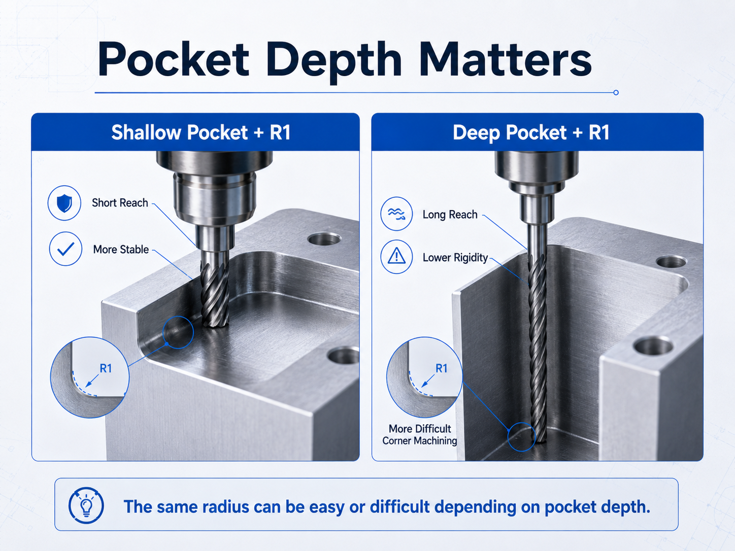
Pocket depth is very important when evaluating an internal corner radius.
Consider two parts that both require an R1 corner.
The cutter only needs to reach a short distance.
The tool can remain relatively rigid.
Machining may be straightforward.
The same small cutter must reach much farther into the part.
This can create several problems:
The radius is still R1.
The difference is the required tool reach.
This is why an internal radius should not be evaluated by itself.
A better question is:
How deep is the corner, and what cutter is needed to reach it?
| Design Condition | Cutter Selection | Machining Effect | Cost Risk |
|---|---|---|---|
| Larger internal radius | More freedom to use a larger cutter | Usually easier and more stable machining | Lower risk of extra operations |
| Smaller internal radius | May require a smaller cutter | May need extra passes and corner clearing | Higher risk of added machining time |
| Very sharp internal corner | Standard end milling may not be enough | May require plunge cutting, EDM, or design changes | Higher risk of extra processes |
These are general machining trends.
The actual result depends on the part geometry, material, tolerance, quantity, machine, and tooling.
A very sharp internal corner may not be practical with standard end milling.
There are several possible solutions.
If the feature is accessible, the manufacturer may use a smaller cutter to remove the remaining corner material.
This is often the simplest solution.
However, the cutter must still have enough rigidity and reach.
Plunge milling means the cutter moves mainly in the axial direction, or downward into the material.
For some corner features, this method can remove material that is difficult to reach with a normal side-cutting toolpath.
In our shop, plunge milling can be used to clear certain internal corners.
For suitable parts, it may be faster than moving directly to EDM.
However, plunge milling is not suitable for every corner.
The part geometry and cutter access must be checked first.
Wire EDM uses an electrically charged wire to remove conductive material.
It can be useful when a sharp corner is required in a through feature.
In our factory, through features with very sharp internal corners may be considered for wire EDM.
The wire must be able to pass through the feature.
Sinker EDM uses a shaped electrode to remove conductive material.
It can reach features that a milling cutter cannot easily access.
In our shop, sinker EDM may be used to clear sharp corners in blind cavities.
This process takes more time in our production environment and can increase cost.
For this reason, we usually evaluate other machining options before using sinker EDM for high-volume parts.
This is our factory experience, not an industry-wide rule.
Consider a machined housing with a large internal pocket.
Most of the pocket can be machined with a larger cutter.
However, the drawing requires R1 corners.
In our shop, an R1 corner may be finished with a Ø2 mm cutter.
The machining process could then include:
Now assume the R1 corner is not required for assembly or function.
If the designer increases the radius, the manufacturer may be able to use a larger cutter for more of the machining process.
This may reduce the need for a separate small-tool operation.
The cost benefit does not come from the larger radius alone.
It comes from a simpler tooling and machining strategy.
The actual saving must be evaluated from the complete part.
If the corner does not have an important functional requirement, consider increasing the radius.
A larger radius gives the manufacturer more freedom to use larger and more rigid cutters.
This is especially useful in deep pockets.
A small radius may look like a minor detail on the drawing.
In production, it can determine the smallest cutter required for the feature.
Before specifying a tight radius, ask whether it is needed for:
If it has no clear function, a larger radius may be easier to manufacture.
Do not evaluate R0.5, R1, R2, or R3 by radius alone.
Also check:
A small radius in a shallow pocket may be easy.
The same radius in a deep pocket may be much more difficult.
Using many different internal radii on one part may require more cutters.
If function allows, using the same radius in several locations can simplify tooling and programming.
Sometimes a square component must fit into a milled pocket.
A designer may think the pocket needs a perfectly sharp corner.
In some cases, a corner relief or dog-bone feature can provide the required clearance.
This allows the manufacturer to use a more practical cutter.
If a small radius is necessary, identify it clearly on the drawing.
The manufacturer can then focus on keeping that feature unchanged.
Other non-critical corners may be adjusted for easier machining.
This makes DFM communication more effective.
A small internal corner radius is not automatically expensive.
It becomes more important when it forces the manufacturer to change the machining process.
The biggest cost risks usually appear when the design requires:
If the corner radius has no functional purpose, increasing it may make the part easier to machine.
For production parts, this can simplify the manufacturing process and reduce unnecessary machining work.
It can. A smaller radius may require a smaller cutter, extra corner-clearing passes, or another machining method. The actual cost impact depends on the full part geometry.
A standard end mill is round. Its shape naturally leaves a radius where two internal walls meet.
From a geometric point of view, R0.5 limits the cutter diameter to about 1 mm, while R1 limits it to about 2 mm. In our shop, Ø1 mm and Ø2 mm cutters are commonly used for these features. Actual tool selection must be confirmed for each part.
The small radius requires a small cutter. A deep pocket also requires longer tool reach. A small cutter with a long reach is less rigid and more sensitive to vibration and deflection.
Not in every case. A manufacturer may use a smaller cutter, plunge milling, corner relief, wire EDM, sinker EDM, or another method. The right process depends on the feature.
Copyright © Dongguan BIE Hardware Co., Ltd - Privacy policy
