
Thin walls can make CNC machining less stable, but they do not automatically make every part inaccurate or expensive. Problems arise when a wall does not have enough rigidity or support to resist cutting forces, vibration, clamping or stress redistribution during material removal.
The CNC machine may follow the correct programmed path while the thin wall itself moves away from its expected position. Holding the required dimensions may then require additional process planning, machining passes, workholding or inspection. Those changes--not wall thickness alone--are what can increase machining cost.
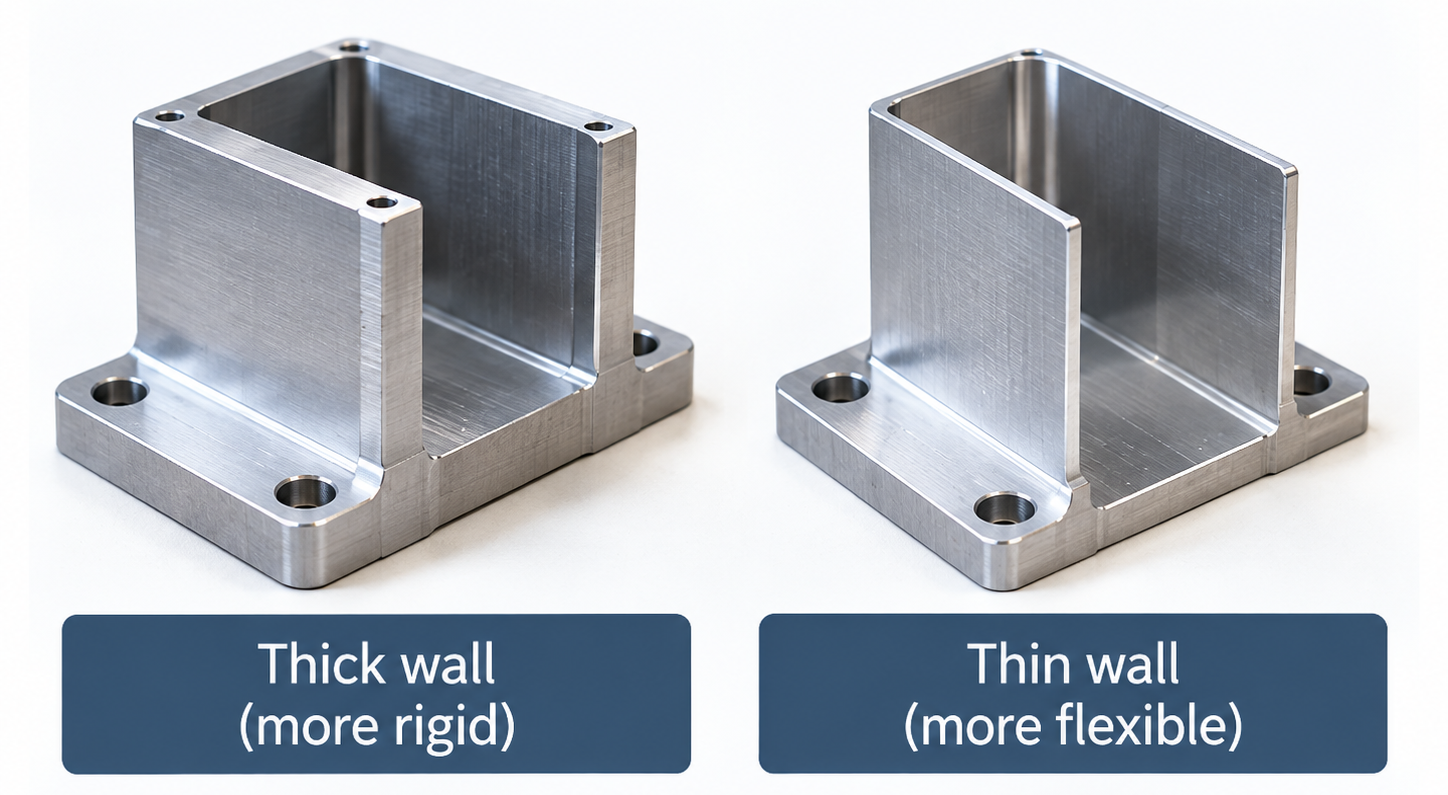
A thin wall is a feature that is relatively flexible compared with the forces acting on it during machining. It cannot be defined by one universal thickness.
A short wall connected to surrounding material may remain stable at a thickness that would be risky for a tall, long or unsupported wall. Material, geometry, tolerance, tool access, clamping and quantity can all change the result.
Minimum-wall values can help screen a design, but they are not universal guarantees. The complete drawing still needs to be reviewed before manufacturability can be confirmed.
Thin walls can affect accuracy when they move or change shape during machining. The most important mechanisms are cutting-force deflection, vibration and distortion after material removal.
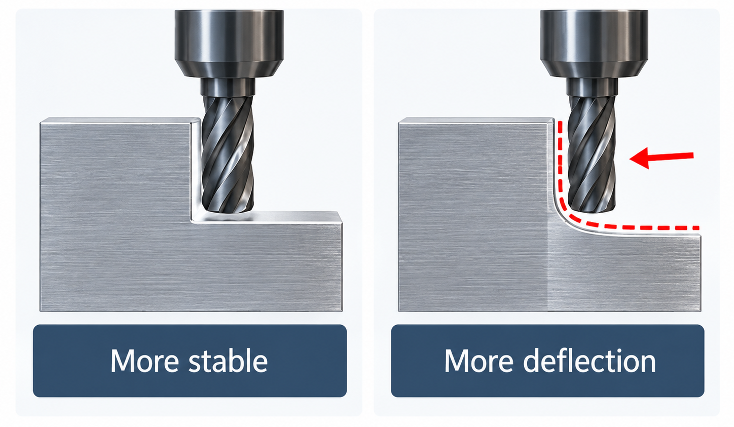
A cutting tool applies force as it removes material. A solid section usually resists this force better than a thin, unsupported wall.
If the wall moves away from the cutter, the actual amount of material removed may differ from the programmed amount. The wall may spring back after the cutter passes. This can contribute to thickness variation, taper or profile error.
Research on thin-wall milling identifies elastic deformation under cutting forces as an important source of dimensional error. The machine can therefore be positioned correctly while the flexible workpiece is not exactly where the program assumes it is.
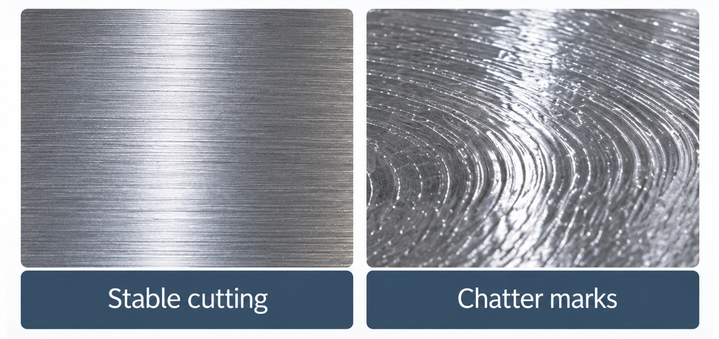
A flexible wall may vibrate when the cutting edges repeatedly contact it. This vibration is often called chatter.
Chatter can leave visible surface marks and make tool–workpiece contact less stable. It may affect both dimensional control and surface finish. The risk depends on wall geometry, material, support, tooling and machining conditions. It should not be assumed that every thin wall will chatter.
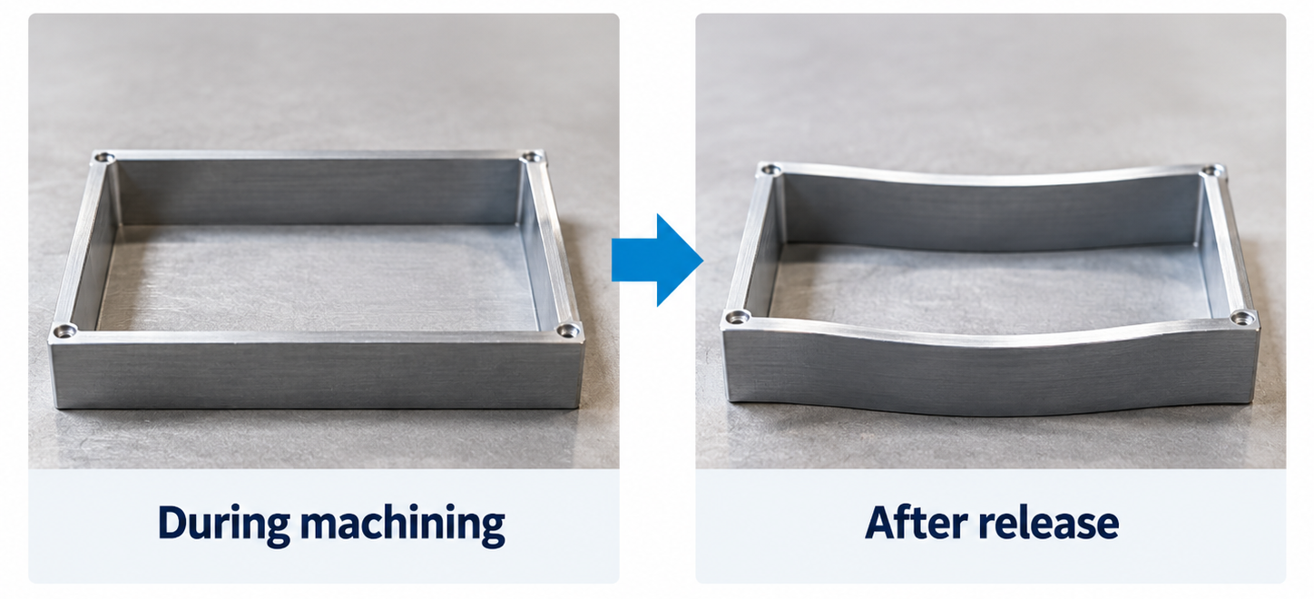
Raw material may contain residual stress from earlier manufacturing processes. Removing a large amount of stock can disturb the previous stress balance.
The remaining thin structure may change shape during machining or after it is released from the fixture. This is different from temporary elastic movement under the cutter. Studies of thin-walled parts have shown that material removal and residual-stress redistribution can contribute to machining distortion.
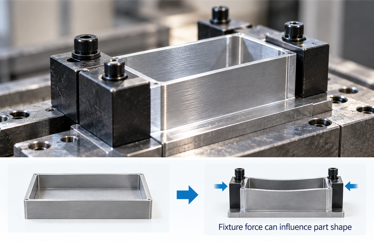
A fixture must hold the workpiece securely. However, a flexible wall can be sensitive to clamping force.
If the fixture temporarily changes the part's shape, the part may move again after the clamping force is removed. Whether this matters depends on the part, fixture and drawing requirements. It is not a problem that should be assumed for every thin-wall component.
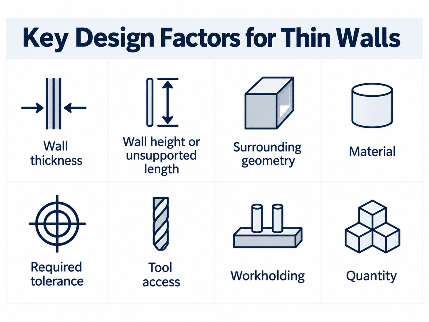
Wall thickness should never be reviewed alone. A useful DFM review also considers support, length, material, tolerance and access.
|
Design factor |
Why it matters |
|
Wall thickness |
A thinner section usually has less resistance to bending. |
|
Wall height or unsupported length |
A long free-standing feature can move more easily than a short supported one. |
|
Surrounding geometry |
Ribs, corners and connected surfaces can add support. |
|
Material |
Different material-and-geometry combinations respond differently to cutting and clamping forces. |
|
Required tolerance |
A physically machinable wall may still be difficult to hold within a tight requirement. |
|
Tool access |
A wall inside a deep or restricted area may be more difficult to reach with a rigid setup. |
|
Workholding |
The part must be held securely without creating unacceptable distortion. |
|
Quantity |
A method that is manageable for a small batch may not be practical for a larger production run. |
Thin walls increase cost only when they change the manufacturing work or production risk. The cost does not rise simply because the wall is thin.
A stable feature may allow material to be removed efficiently. A flexible feature may require more cautious material removal or additional finishing passes.
Machining time is a major CNC cost driver. Industry DFM guidance also identifies special tooling, stricter quality control and extra operations as possible cost contributors for difficult thin-wall features.
The order in which material is removed can affect how much support remains around a wall. A thin-wall part may require more process planning than a conventional solid part.
The correct sequence cannot be selected from a general article. It depends on the drawing, material, machine, tooling and fixture.
Some geometries may require a different fixture or additional support. This can add setup or engineering work.
Our experience with long thin-walled tubes shows why support must be evaluated carefully. When support is inadequate, a tube may move in the workholding setup or deform during machining. This risk depends on the complete geometry and setup, so it must be assessed from the drawing rather than assumed from wall thickness alone.
A flexible feature may require additional dimensional checks. There may also be greater risk of rework or rejection if the feature does not remain stable.
No fixed cost increase, scrap rate or cycle-time percentage can be stated without actual production data.
|
Drawing condition |
Appropriate response |
|
The wall is adequately supported and the requirements appear practical |
Continue with normal process review. |
|
The wall is thin, long or tightly toleranced, but may still be feasible |
Perform a detailed DFM and production review. |
|
The wall is unlikely to remain stable enough to meet the drawing |
Recommend a design change or another process. |
|
Reliable production cannot be established |
Do not accept the part as designed. |
Our engineering review starts with the complete customer drawing. We evaluate wall thickness together with unsupported length, surrounding geometry, material, tolerance, tool access, workholding and order quantity. This drawing-based approach allows us to identify the real manufacturing risks before production begins.
Based on our manufacturing experience, walls below 0.5 mm require particularly careful feasibility review. The number is not a universal machining limit. A short, well-supported feature may behave very differently from a long or unsupported wall, even when both have the same nominal thickness.
Long thin-walled tubes require adequate support to remain stable during machining. We therefore evaluate the support condition and workholding risk as part of production-feasibility review, especially when the geometry provides limited rigidity.
For repeat or higher-volume production, feasibility is not enough by itself. The process must also be capable of maintaining dimensional consistency across the required quantity. When the drawing presents an unacceptable manufacturing risk, we identify the concern before production and recommend a practical design or process adjustment rather than making an unsupported production commitment.
Where product function permits, increasing wall thickness is often the most direct DFM improvement. The final recommendation still depends on the complete drawing and functional requirements.
Keep Walls as Thick as Function Allows
Do not reduce a wall further than the product needs. Increasing thickness can improve rigidity and may make the feature easier to manufacture.
A short, supported wall is generally more stable than a long free-standing wall. Where the design permits, reduce wall height or length or connect the wall to supporting geometry.
Ribs, gussets or connected surfaces may improve rigidity. Their shape and position still require a drawing-based DFM review.
A wall may be physically machinable but difficult to produce economically when paired with an unnecessarily tight tolerance.
Identify the dimensions that are function-critical. Use practical requirements for noncritical features.
Wall thickness alone is not enough to determine feasibility. The manufacturer needs the complete geometry, material, tolerances, quantity and functional requirements.
For a very thin feature, machining from solid stock may not always be the most practical production route.
For suitable plastic parts, injection molding may be evaluated. For suitable metal parts, die casting may be evaluated. These options are not automatic replacements for CNC machining. Geometry, material, quantity, tooling investment and final requirements must be reviewed before selecting a process.
Thin walls affect CNC machining when the remaining structure is not rigid or well supported enough for the required operation and tolerance.
Cutting force may move the wall. Vibration may affect the surface. Clamping or residual-stress redistribution may change the final shape. Controlling these effects can require additional planning, machining, workholding or inspection, which may increase cost.
The right question is not simply, "Is this wall too thin?"
A more useful question is:
Can the complete geometry remain stable enough to meet the drawing requirements at the required quantity?
The answer requires a drawing-based DFM review.
No. Accuracy is affected when a wall moves, vibrates or distorts enough to interfere with the required dimensions or surface finish. A short, supported wall with practical tolerances may be manageable.
No. Cost increases only when the feature requires additional planning, machining passes, workholding, inspection or risk control.
There is no universal minimum. The practical limit depends on material, wall height, unsupported length, geometry, tolerance, access and factory capability.
Based on our manufacturing experience, walls below 0.5 mm require particularly careful feasibility review. This is an experience-based screening point, not a universal industry limit or a guarantee for every geometry.
Long thin-walled tubes need adequate support during machining. Our production experience shows that insufficient support can allow the tube to move in the workholding setup and may also cause deformation. The actual risk must be assessed from the complete drawing and planned setup.
Yes. A process that is practical for a prototype or small batch must also maintain dimensional consistency when production quantity increases. We evaluate quantity together with geometry, material, tolerance, workholding and inspection requirements before confirming production feasibility.
Possibly. A suitable plastic part may be evaluated for injection molding, while a suitable metal part may be evaluated for die casting. The decision still depends on geometry, material, quantity, tooling investment and final requirements.
Send us your complete drawing, material specification, tolerance requirements and order quantity. Our engineering team will review the thin-wall geometry, identify the main manufacturing risks and provide practical DFM feedback before quotation and production planning.
Copyright © Dongguan BIE Hardware Co., Ltd - Privacy policy
