Home > Products > More > Aluminum Extrusion
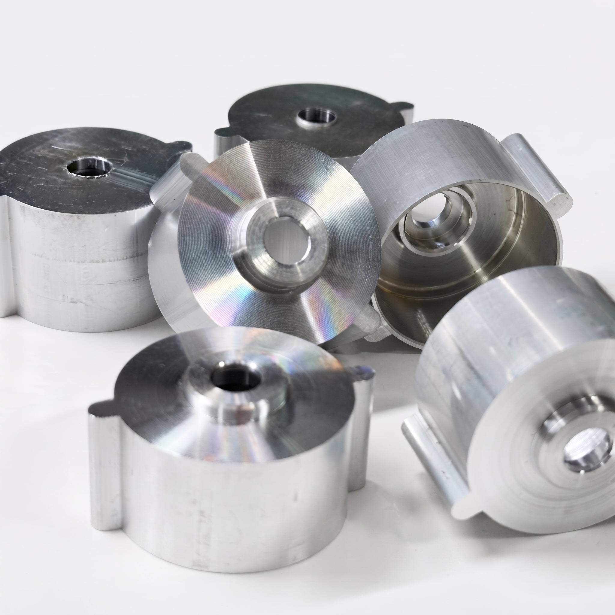
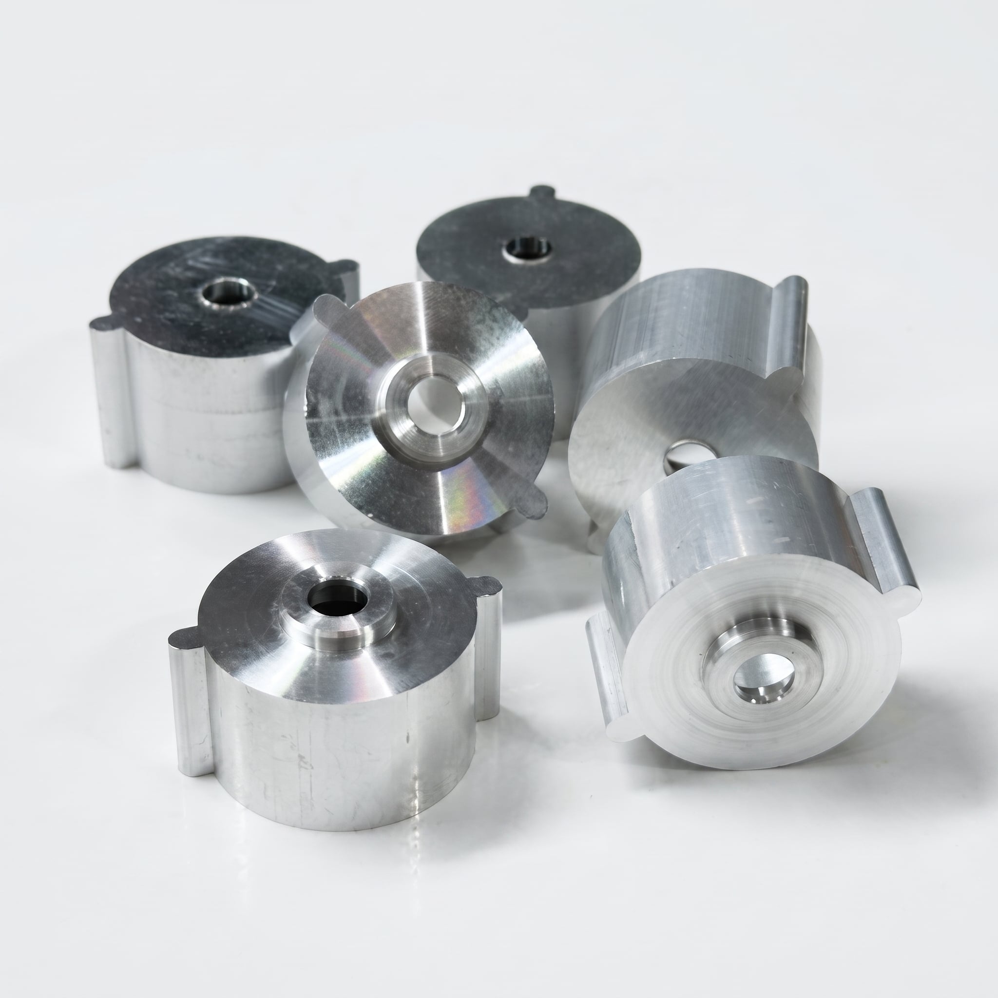
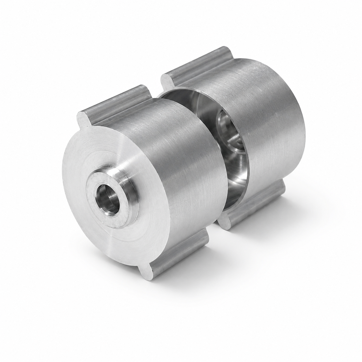
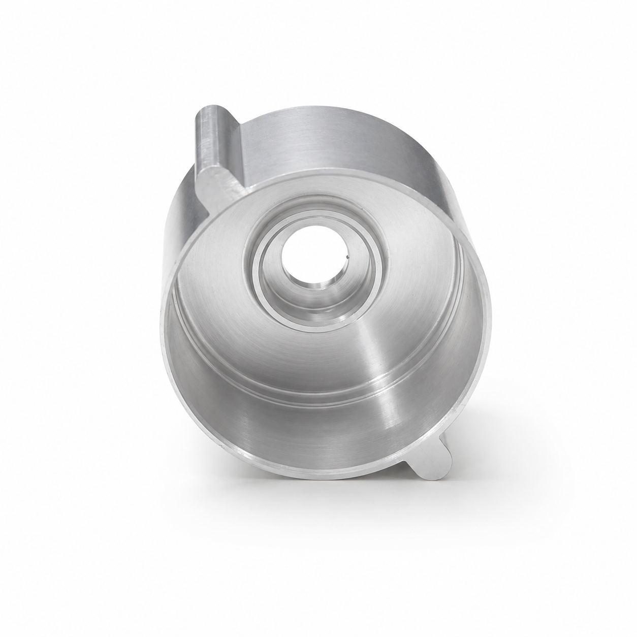
Manufactured from aluminum extrusion and precision CNC machining, this custom motor housing is built to customer drawings for UAV, drone and compact electric motor assemblies. Critical bores, end faces, mounting features and internal interfaces are machined and inspected for repeatable production.
This aluminum UAV motor housing is a custom-manufactured component produced from an extruded aluminum profile and finished by precision CNC turning and milling.
The extrusion forms the primary external profile of the housing, while CNC machining controls the center bore, internal steps, end faces, mounting tabs, holes and other functional interfaces specified in the customer’s drawing.
BIE manufactures these motor housings to order rather than supplying a standard off-the-shelf product. We support extrusion feasibility review, machining allowance planning, tolerance analysis, surface finishing and dimensional inspection for engineering samples, pilot runs and repeat production.
| Item | Available Options |
|---|---|
| Product Type | Custom UAV and drone motor housing |
| Material | Extruded aluminum alloy |
| Common Grades | 6061, 6063 and 6082; other extrudable grades reviewed according to the drawing |
| Manufacturing Process | Aluminum extrusion, cutting, CNC turning, CNC milling, drilling, deburring and finishing |
| General Tolerance | ISO 2768-mK unless otherwise specified |
| Precision Tolerance | ±0.01 mm for precision features; critical dimensions down to ±0.005 mm after engineering review |
| Surface Finishes | As machined, anodizing, hard anodizing, sandblasting, polishing, brushing, painting and laser marking |
| Inspection | CMM, optical measurement, hardness testing and surface roughness inspection |
| Production Type | Engineering samples, pilot runs and repeat batch production |
| Drawing Formats | STEP, STP, IGES, X_T, DXF and PDF |
| Sample Lead Time | Typically 3–7 days when suitable extrusion material is already available |
| Custom Extrusion Tooling | Tooling feasibility and lead time quoted separately |
| Production Lead Time | Typically 20–35 days depending on quantity, tooling, finish and inspection requirements |
Aluminum extrusion is suitable for motor housing designs that have a consistent longitudinal profile. It creates the primary external shape before precision machining, reducing the amount of material that must be removed from a solid billet.
CNC turning and milling are then used to produce the features that require tighter dimensional control, including:
For repeat production, this combined process can improve material utilization and production consistency when the geometry and order volume justify extrusion tooling.
For lower-volume projects, frequently changing designs or geometries that are not suitable for extrusion, machining the housing directly from aluminum billet may be more practical. BIE can evaluate both manufacturing routes during the DFM review.
The functional performance of a motor housing depends on more than its overall diameter and length. The following features should normally be identified on the technical drawing:
BIE performs in-process and final inspection according to the approved drawing. CMM reports, dimensional inspection reports and First Article Inspection documentation can be provided when required.
Our engineering team reviews the CAD model, drawing, material grade, tolerances, surface finish and expected production quantity.
For extrusion-based designs, we also evaluate:
The aluminum profile is extruded according to the approved cross-section. Material grade, heat treatment condition and dimensional allowance are selected according to the mechanical, machining and finishing requirements.
The extrusion is cut into individual blanks with sufficient allowance for facing, turning and other machining operations.
CNC turning is used for circular features such as bores, end faces, internal steps and concentric surfaces.
CNC milling and drilling are used for mounting tabs, holes, slots, flats and other non-rotational features.
Sharp edges and machining burrs are removed before cleaning and surface treatment. Available finishes include anodizing, hard anodizing, sandblasting, polishing, brushing and laser marking.
Critical dimensions are inspected according to the drawing and agreed quality requirements. Finished housings are cleaned and individually protected to prevent scratches and impact damage during transportation.
Aluminum is commonly selected for UAV motor housings because it provides a practical combination of low weight, machinability, corrosion resistance and surface-finishing compatibility.
Common material options include:
Suitable for general structural motor housings requiring balanced strength, machinability and anodizing performance.
Frequently used for extrusion profiles with more complex cross-sections and good surface-finishing requirements.
Suitable for components requiring higher structural strength, subject to extrusion and machining feasibility.
The final alloy and temper should be selected according to the required strength, weight, heat transfer, anodizing appearance and operating environment.
Retains visible CNC tool marks and is suitable for internal parts or applications where no decorative finish is required.
Improves corrosion resistance and allows different appearance requirements while maintaining the aluminum surface texture.
Suitable for surfaces requiring improved wear resistance. Dimensional allowance should be considered for precision bores and mating features.
Produces a more uniform matte appearance and reduces the visibility of minor machining marks.
Used when a directional or reflective metal surface is required.
Part numbers, batch codes, logos and traceability information can be marked according to customer requirements.
These custom aluminum motor housings can be used for:
Each housing can be manufactured according to the customer’s design, including:
BIE applies dimensional control throughout the manufacturing process, including:
Inspection documentation can be prepared according to the customer’s project requirements.
No. The housing shown is a custom manufacturing example. Dimensions, internal structures, mounting features and surface finishes are produced according to each customer’s drawings.
It depends on the geometry. If an existing aluminum extrusion or standard-sized blank is suitable, the housing may be machined without new extrusion tooling. Otherwise, a custom extrusion die or machining from solid billet may be required.
Extrusion is generally more suitable when the part has a consistent cross-section and the expected production volume can justify the tooling. Billet machining may be more practical for lower quantities, design validation or frequently changing geometries.
General dimensions can follow ISO 2768-mK. Precision features can normally be controlled to ±0.01 mm, while selected critical dimensions may reach ±0.005 mm after drawing, material and process review.
Yes. Bore diameter, concentricity, roundness and runout can be inspected according to the drawing. The achievable values depend on part geometry, datum design, wall thickness and clamping conditions.
STEP, STP, IGES or X_T files are recommended for the 3D model. A PDF technical drawing should also be provided when the part includes specific tolerances, threads, surface roughness or geometric tolerances.
Yes. Clear, black and color anodizing, hard anodizing and sandblasting plus anodizing are available. Precision mating dimensions should identify whether they must be masked or compensated for coating thickness.
Yes. BIE supports engineering samples, pilot runs and repeat production, with inspection and process controls established according to the approved drawing.
Upload your STEP file and technical drawing with the required material, tolerances, surface finish and estimated production quantity.
Our engineering team will review the extrusion and CNC machining requirements and provide manufacturing feedback, lead time and a detailed quotation.
Copyright © Dongguan BIE Hardware Co., Ltd - Privacy policy