CNC milling quality control connects the drawing requirements with material verification, setup checks, first-piece inspection, checks during production and final release. Agree what will be measured, when it will be checked, which records are required and how deviations will be handled before the order begins.
For overseas buyers, this creates evidence that can be reviewed across locations. A photograph shows the part's appearance. A dimensional report records specified measurements. An assembly evaluation answers a further question about the component in its intended application. Define the evidence needed for each requirement.
This guide explains how to build that agreement for a milled housing, bracket, plate or other custom component. It focuses on practical handovers between purchasing, engineering, manufacturing and receiving inspection.
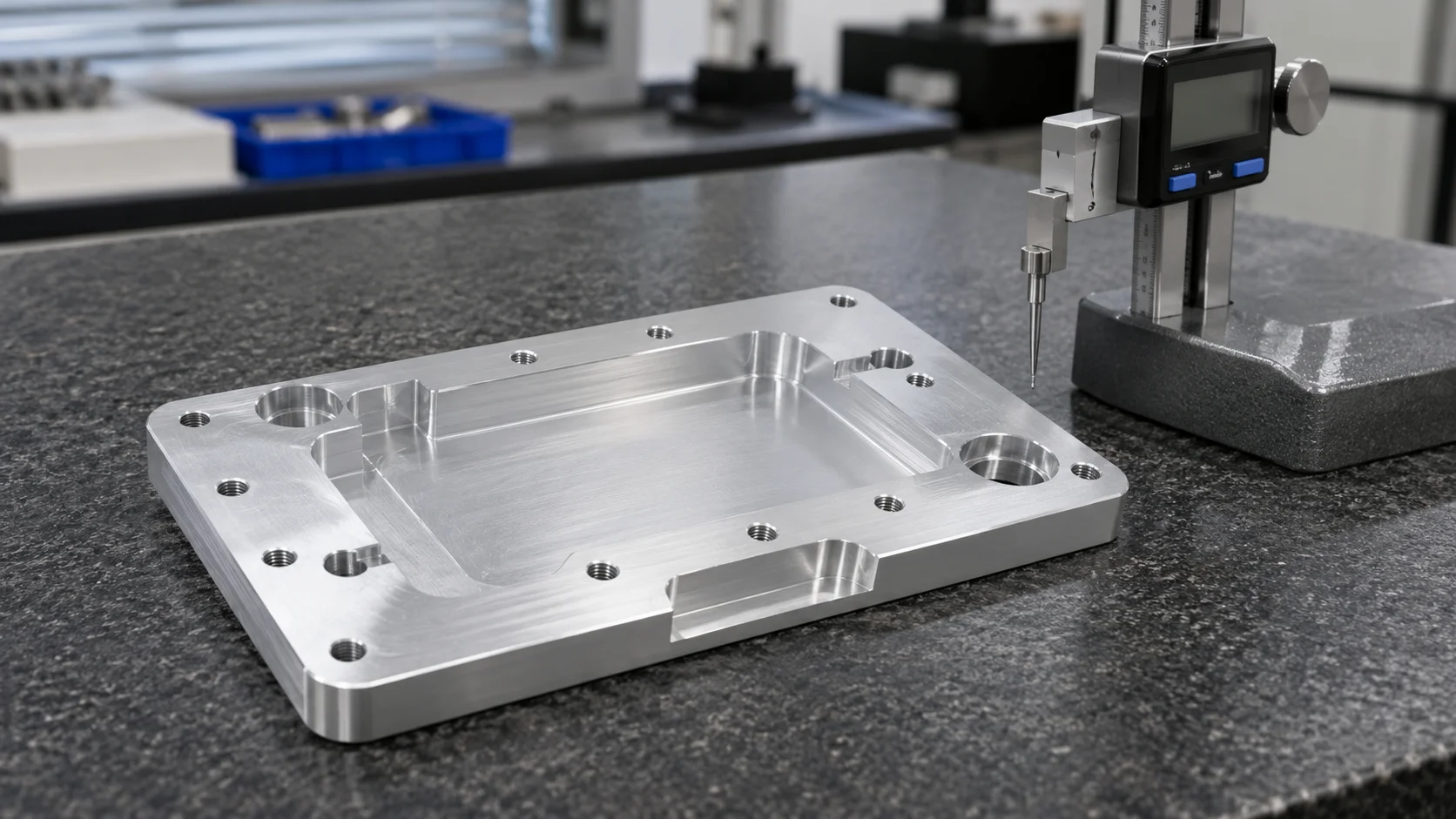
Begin with one approved drawing and model revision. Resolve conflicting dimensions, missing specifications and differences between the model and drawing before manufacturing release.
Identify the features that control the product application. A bore may locate a shaft. A mounting face may establish the component's orientation. A pocket may provide clearance while a separate interface controls the assembly. These features need different checks.
Geometric dimensioning and tolerancing expresses requirements for form, orientation and location as well as size. Identify the applicable drawing convention and explain any interpretation that affects acceptance.
Create a short characteristic list that both teams can use. Include the reference, acceptance requirement, inspection stage, proposed method and record required. The table below illustrates its structure.
| Characteristic | Acceptance question | Planning detail |
| Locating bore | Does its size meet the drawing? | Suitable size measurement and reporting |
| Hole pattern | Is its location correct relative to the specified references? | Alignment and geometric evaluation |
| Mounting face | Does its form meet the requirement? | Support condition and measurement strategy |
| Thread | Does it meet the specified thread requirement? | Appropriate gauge and inspection scope |
| Finished surface | Does it meet texture or appearance requirements? | Specified surface, method and processing stage |
Agree which document controls if a question arises. Keep approved clarifications with the order so manufacturing and receiving inspection use the same interpretation.
Material verification starts with the specified grade, condition and stock form. State which supplier documents are required and how they must connect to the material used for the order.
A material certificate can provide evidence about the identified material. Its usefulness depends on the specification, information recorded and connection to the supplied stock. Ask what identification will be retained through cutting and processing where traceability is required.
For a heat-treated material, confirm whether the required condition applies to the starting stock or finished component. For a plastic part, explain any agreed conditioning requirement that affects acceptance.
Record who will review discrepancies. If the available material differs from the order, the substitution needs approval before it becomes the production basis. Keep the agreed decision visible to the people preparing the program and inspection plan.
Also confirm which customer-supplied components, samples or mating parts are needed for later checks. Their identity and revision should remain clear throughout the order.
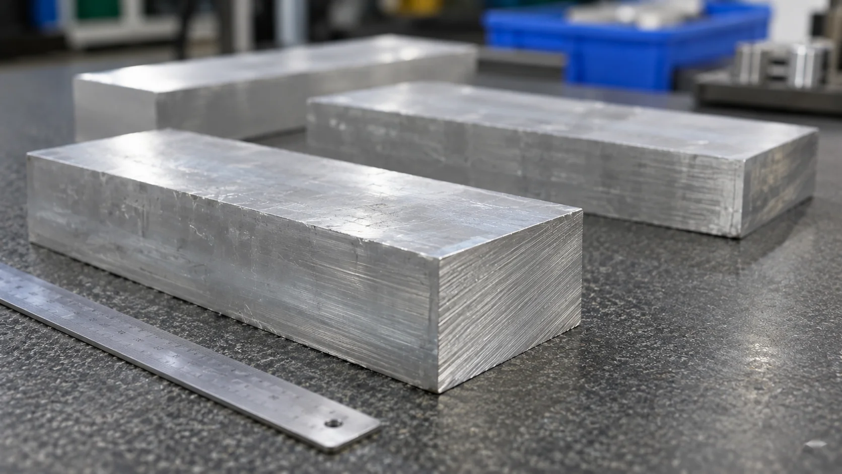
First-piece inspection examines the output from an established setup. It helps identify whether the program, workholding, tools and interpretation are producing the required characteristics before the run continues.
Agree what the initial inspection covers and who can release production. For a new component, ask which requirements need verification on the first piece and which will be checked after subsequent operations.
The phrase “first article inspection” can refer to different contractual documentation requirements. Specify the required format, characteristics and approval conditions. Where an industry or customer procedure applies, identify it in the order.
An early report should identify the part, revision and inspected condition. A pre-coating measurement and a finished-part measurement answer different questions. Keep that distinction visible when some checks happen before all processing is complete.
The wider purpose is to control variation throughout manufacturing. Preparation, checks during processing and final verification each contribute to that task.
Agree how the supplier will monitor characteristics that can change as production proceeds. Relevant events may include a tool replacement, fixture adjustment, program revision or restart.
Identify what should happen when a result approaches an agreed action point or falls outside a requirement. The plan should state who reviews the result and how potentially affected parts will be identified.
Choose checking frequency according to the component and agreed control plan. Ask the supplier to explain the proposed frequency for the relevant features. A generic interval gives limited information about how a particular requirement is controlled.
Machine-tool probing can support workpiece setting and selected checks during processing. Its role depends on the machine, software and measurement task. Ask which checks are proposed and how they relate to the final acceptance plan.
Where statistical records are required, identify the characteristic, data collection and customer approval criteria. The required evidence should be clear enough for both teams to understand what a reported result demonstrates.
Preparing a new milling order? Send Your Requirements to BIE. Include the drawing revision, critical characteristics and required inspection documents so the quotation can address manufacturing and acceptance together.
Select the inspection method for the characteristic, tolerance and access available. The instrument's display resolution is one consideration within a larger measurement task.
A suitable micrometer, gauge or other instrument may verify a particular size. Measuring the relationship between several features requires a strategy that addresses the drawing references and geometry.
A coordinate measuring machine, or CMM, can support suitable dimensional and geometric evaluations. Its program, probe arrangement, alignment and access must suit the specified characteristic. Ask what the proposed report will show.
Datums are references used to establish specified relationships. The inspection alignment should represent the drawing's requirements. Using a convenient surface without considering its specified role can produce results that answer a different question.
Consider cleanliness, support, temperature and the condition of the part. A burr at a contact point or distortion from clamping can change the measurement. Discuss these factors when comparing supplier and receiving-inspection results.
Measurement uncertainty describes the doubt associated with a result. It depends on the complete method and conditions. When results lie close to an acceptance limit, ask the quality teams to agree how conformity will be evaluated.
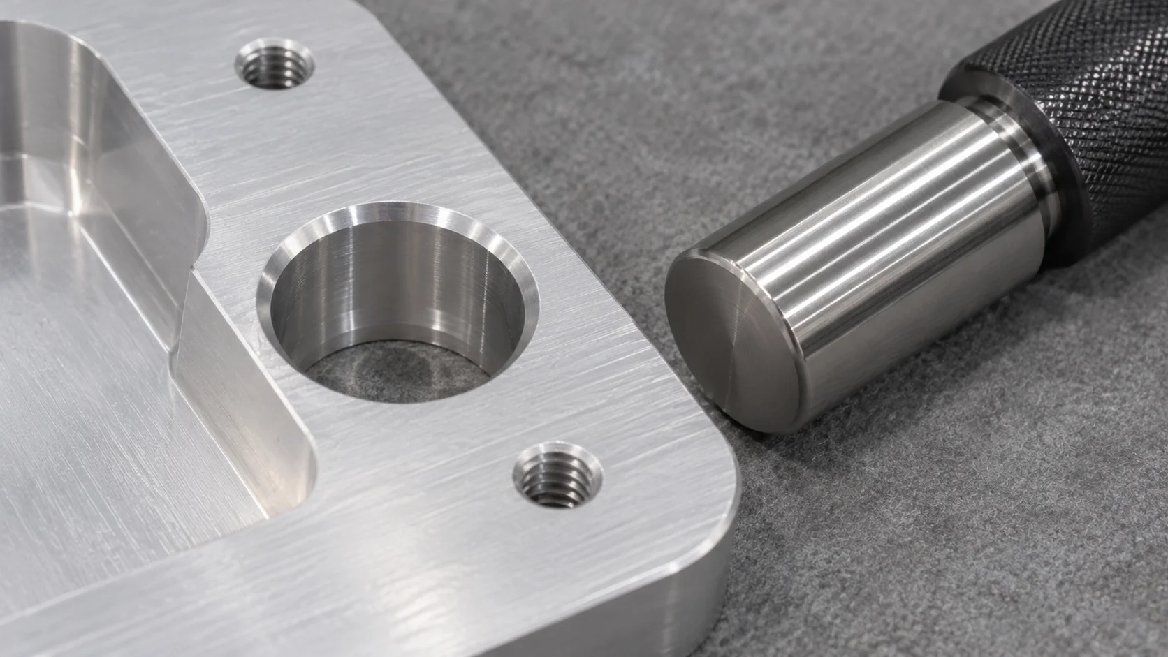
Surface texture, appearance and dimensional fit need their own acceptance definitions. Identify the surfaces affected and the condition in which each will be checked.
Ra describes an arithmetic average of roughness-profile heights. It provides a particular texture measure. A surface can also have requirements for appearance, local defects or other functional characteristics. State the parameter and measurement requirements called for by the drawing.
For cosmetic areas, agree a suitable reference and viewing conditions. Identify acceptable variation using approved samples where appropriate. Color names and finish names alone can leave the buyer and supplier expecting different results.
If the part receives anodizing, coating, heat treatment or another operation, decide which characteristics require checking afterward. A machining-stage result should remain identified with that stage. The delivered component must be evaluated against the requirements that apply to its finished condition.
Include installation preparation in this discussion. Explain mating parts, fasteners and features that require protection or cleanliness before assembly. Where factory testing or assembly checks are requested, define the setup, supplied mating components and results to record.
Final inspection verifies the agreed release requirements. Establish the inspected characteristics, quantity, recording scope and response to a failed check before shipment.
“100% inspection” needs a defined scope. It may describe every part being checked for selected characteristics. State which characteristics require individual results and what evidence must accompany the order.
For sampling, agree the lot definition and applicable plan. Record the inspected quantity and the action following a nonconforming result. Acceptance sampling uses sample information to support a lot decision.
An inspection report should let the buyer connect a result to a requirement and an identifiable part or lot. The following fields help make that connection reviewable.
| Report field | Why the buyer needs it |
| Part number and revision | Connects the record to the approved product definition |
| Lot or part identification | Identifies the inspected delivery or component |
| Characteristic reference | Connects the entry to the drawing or agreed list |
| Requirement and units | Shows the basis for acceptance |
| Result and inspection scope | States what was measured and the quantity covered |
| Method or instrument reference | Supports review of the measurement approach |
| Inspection condition | Identifies relevant processing or support conditions |
| Disposition and approval | Records release or an unresolved exception |
Request an example format before the order when your receiving system requires particular fields. Agree the actual delivery documentation in the quotation and purchase order.
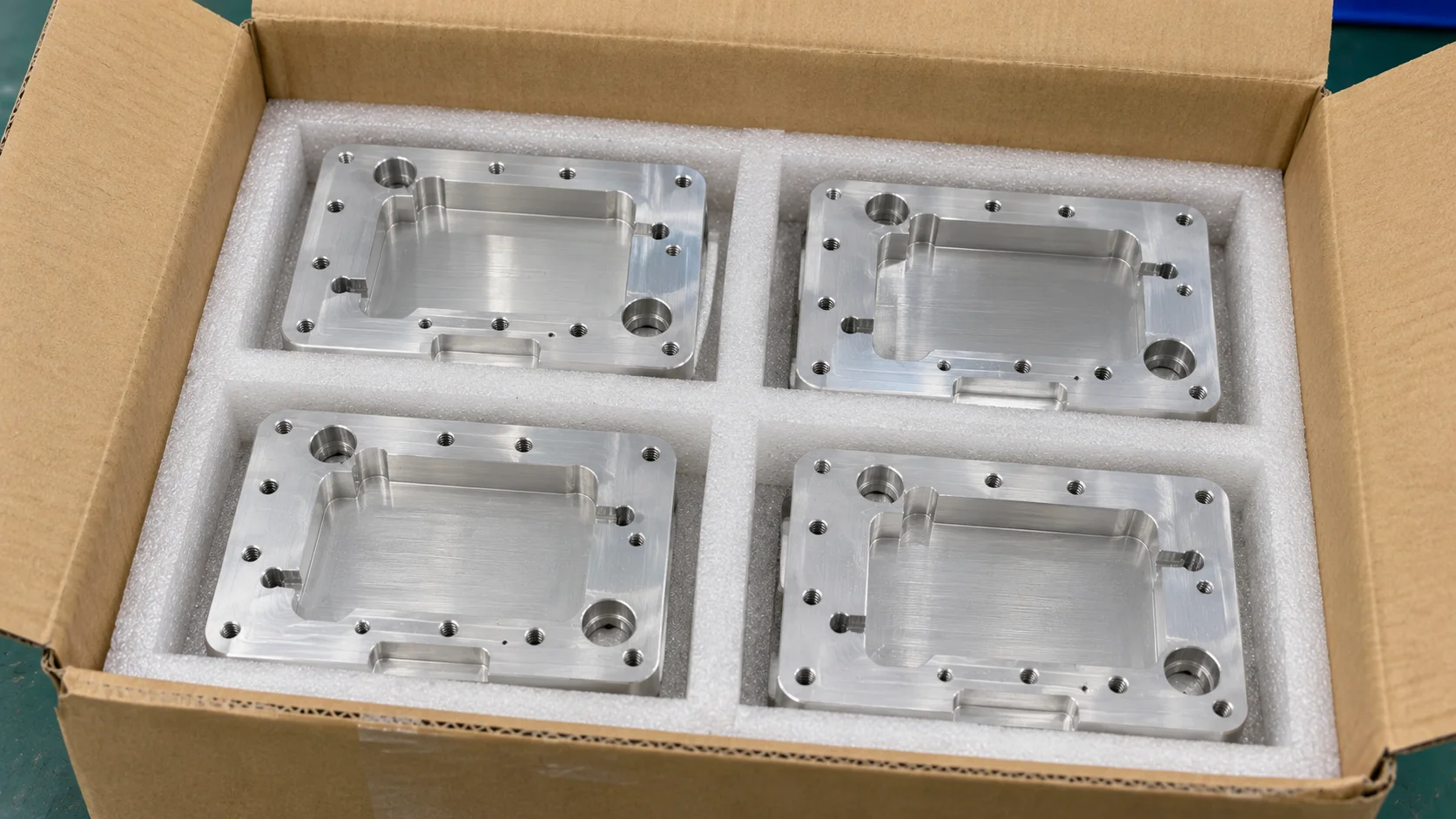
Shipment inspection should include identification, quantity, required documents and packaging condition. Explain which surfaces and interfaces must remain protected during handling and transit.
Finished faces may need separation from adjacent components. Threads, bores and delicate features may require geometry-specific protection. Ask how the proposed packaging supports the relevant requirement and receiving process.
Keep part identification readable and connected to the packing list. If several revisions or lots are shipped, define how they will be separated and labeled. Include any agreed handling or unpacking instructions.
Review the shipment documents before dispatch where the order requires approval. This allows missing records or identification questions to be resolved while the goods remain accessible.
Give the receiving team the same approved characteristic list and documentation requirements used for shipment release. Identify any checks that your facility will repeat and any product tests performed after installation.
If a receiving result differs, retain the part identification and record the condition in which it was measured. Share the method, reference features and relevant photographs with the supplier. A clear record allows both teams to compare like measurements before deciding on disposition.
For a first delivery, plan how the actual mating components will be prepared for evaluation. Confirm their revision, cleanliness and installation conditions. Record whether an assembly observation relates to the supplied part, a mating component or an unresolved requirement. This keeps an installation issue connected to evidence that engineering can review.
Define the communication route for a result that fails an agreed requirement. The initial notification should identify the part, revision, affected quantity and evidence available.
Discuss containment first. Establish how potentially affected work will be separated and how the team will determine which pieces require review. The action should address the relevant production interval or delivery.
Record the authorized disposition. Rework, replacement, further inspection or acceptance by concession each needs a clear decision. A supplier proposal to accept a deviation should receive the customer's required approval before shipment.
For a recurring problem, request an explanation supported by the available evidence and a plan to verify the corrective action. Retain the relevant drawing, inspection and process revisions so the agreed correction remains traceable on future orders.
Consider an illustrative milled mounting plate with two locating holes, clearance holes and a finished mounting face. The assembly needs the locating features to position another component while the clearance holes allow fastening.
The quality discussion begins by identifying those different functions. Agree how the locating-hole sizes and their specified relationships will be measured. Confirm the mounting-face requirement and whether its acceptance applies before or after finishing.
Next, define the initial inspection and checks during production. State what will be recorded for the locating features and how other characteristics will be verified. Include an agreed assembly check if the mating component is available and the order requires it.
Finally, specify protection for the mounting face and identification for the delivered lot. The resulting agreement connects drawing, measurement and shipment. This is a hypothetical planning example, with no claimed BIE customer result or measured performance.
BIE's company profile lists CMM, roughness-measurement equipment, gauges and micrometers among its inspection equipment. It also describes machining, surface-treatment and assembly services. These equipment categories provide a starting point for discussing the inspection task for your component.
BIE's supplied capability information lists milling dimensions up to 1200 × 850 × 600 mm. Part geometry, workholding and access require project review. The measurement arrangement should also be reviewed separately from the machining dimensions.
For a CNC milling enquiry, send the approved drawing, model, material, quantities and critical characteristics. Include the required records and any surface finishing or assembly conditions. Agree the available inspection scope and documentation for the actual order.
Agree a drawing-based inspection plan and request records linked to the part revision and delivered lot. Combine dimensional evidence, material documents and any required appearance or assembly checks. Confirm the report format before production.
The method should suit the specified characteristics and contract. Some features can be verified with suitable gauges or other instruments. A CMM may support geometric relationships requiring an appropriate measurement program.
It supports release of the reviewed setup and scope. Agree further checks during production and at final release to address changes or variation as the order proceeds.
It needs an agreed definition identifying the parts and characteristics checked. Specify which results will be recorded individually and what happens if a part fails.
Compare the drawing interpretation, alignment, instruments, support, temperature and processing condition. Reconcile these factors before deciding whether the difference comes from the part or the measurement method.
A useful CNC milling quality plan connects each important requirement with an inspection stage, suitable method, reviewable record and release decision. Establish that connection before production and keep it visible through finishing, shipment and receiving inspection.
Prepare your milling enquiry with BIE. Send Your Drawing and Inspection Requirements. Include the revision, material, quantities, critical features and required reports so manufacturing and acceptance can be discussed together.
Copyright © Dongguan BIE Hardware Co., Ltd - Privacy policy