Prevent stainless steel CNC machining defects by matching the material condition, cutting process, workholding and inspection plan to the component. When a problem appears, record the affected feature and production stage, investigate the possible causes, then verify the correction against the drawing and application requirements.
A rough bore, a raised edge and a distorted flange can create different assembly problems. Their appearance provides a starting point for investigation. The useful evidence includes the material identity, tool condition, setup, measured results and any subsequent finishing or handling.
For overseas buyers, a practical quality discussion connects those observations to actions the supplier can explain and records your team can review. This guide covers that discussion for custom stainless steel milled and turned parts.
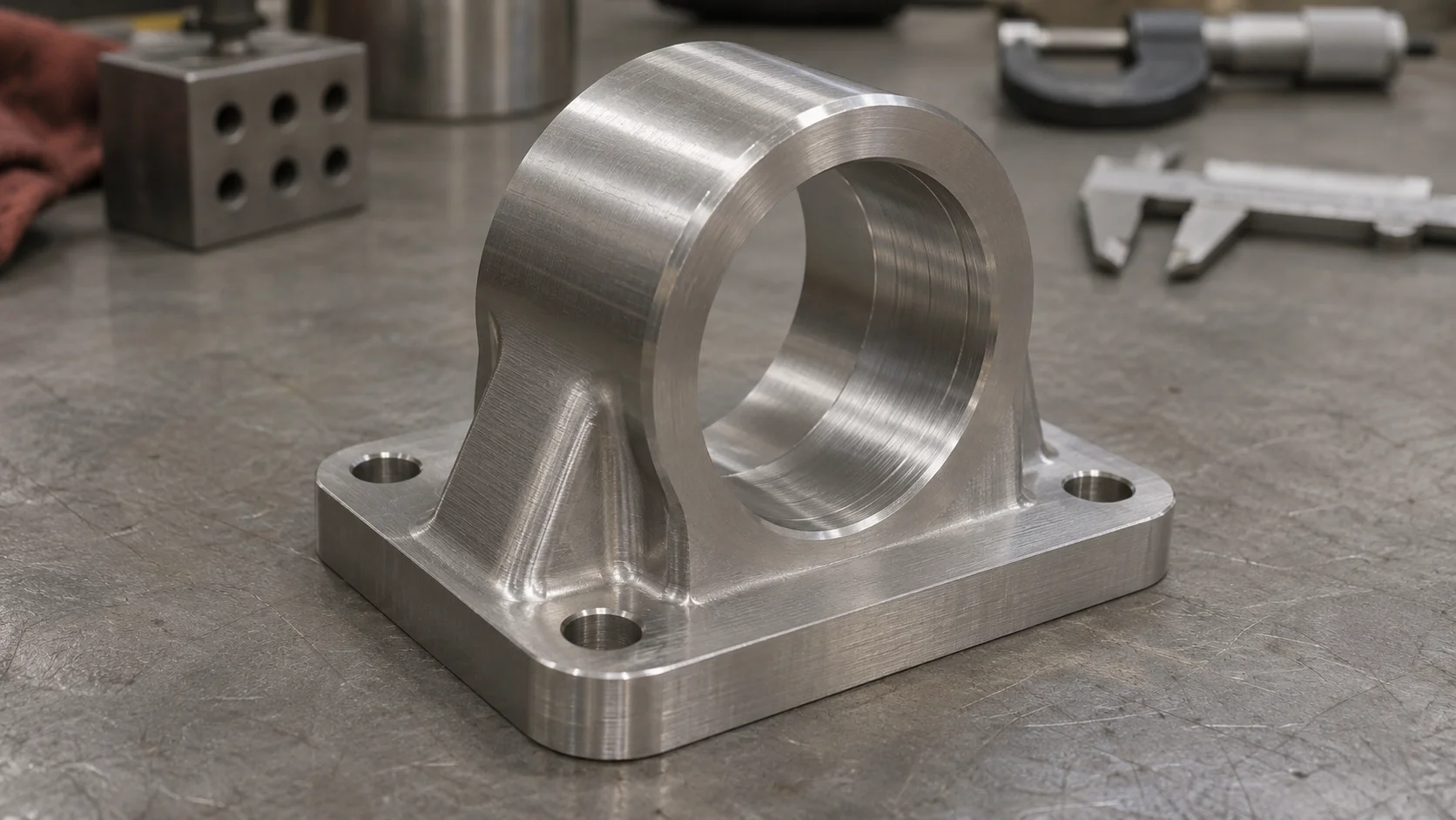
Describe what you can observe before deciding what caused it. Identify the part number, drawing revision, affected quantity and location. Explain whether the concern was found during machining, final inspection, receiving inspection or assembly.
Then connect the observation to a requirement. A visible machining pattern might be acceptable on a concealed surface. A smaller irregularity on a sealing interface could require investigation because of its function.
Use the following table to frame the first conversation. The possible contributors are investigation paths, with the final cause established from the actual evidence.
| Observation | Possible contributors to review | Evidence to request |
| Torn or smeared surface | Material adhesion, cutting-edge condition, chip contact | Close views, affected operation and tool-condition findings |
| Repeated vibration marks | Tool reach, workpiece support, engagement or workholding | Feature geometry, setup and location of the pattern |
| Burrs at an edge or hole exit | Cutting direction, tool condition, material behavior, edge access | Edge requirement and the proposed deburring method |
| Dimensional change | Temperature, clamping, material stress or later processing | Results with measurement and processing conditions |
| Scratches or dents | Chip contact, handling, part separation or packaging | When the damage first appeared and handling records |
| Rust-colored marks | Surface contamination, exposure or material suitability | Material identification, handling and environmental history |
Retain representative affected parts where practical. Cleaning, polishing or reworking everything immediately can remove information needed to understand the problem.
The word stainless covers material families with different machining behavior. Austenitic grades such as 304 and 316, duplex grades, and precipitation-hardening grades should be reviewed against their own material specifications and processing condition.
Confirm the exact grade, product form and required condition. Identify the material documents needed for the order and how the supplied stock connects to those records. If a requirement includes heat treatment, clarify the condition expected during machining and at final acceptance.
An alloy chosen for easier machining may change other properties relevant to the application. Any proposed substitution needs review against corrosion exposure, mechanical duty, joining and the product specification. Obtain engineering approval before making it the production basis.
For repeat orders, retain the approved material definition. If a machining problem coincides with a material change, compare the relevant records before treating the new batch as equivalent to the previous one.
Work hardening is an increase in hardness caused by plastic deformation. It is relevant to austenitic stainless machining because the surface can become harder as it is deformed during processing. Cutting conditions that promote rubbing deserve attention when investigating subsequent cutting difficulty.
Built-up edge is material adhering around the cutting edge. It can change the effective cutting geometry and contribute to an inconsistent surface. Inspect the tool and affected operation when the surface shows tearing or smearing.
A useful review considers the material, tool geometry, cutting-edge condition and actual engagement together. It should establish whether the problem began with a new tool, developed as the run progressed or appeared after a restart.
Ask what the proposed correction changes and what will be checked afterward. A revised tool or cutting strategy needs verification on the relevant feature. The buyer's acceptance requirement remains the drawing, surface specification and intended function.
BIE's stated approach includes selecting suitable carbide or coated cutting tools for the application, checking tool wear and replacing worn tools. The choice is reviewed with the material and operation so the proposed correction addresses the feature being produced.
Record the accepted process change and its verification. That gives the next production run a reference if the same symptom returns.
Cutting fluid can help manage the conditions at the cutting zone and support chip evacuation. Its effect depends on whether it reaches the relevant area, the operation and the tool arrangement. An external flow that looks substantial may still leave a difficult internal feature poorly served.
Ask how the proposed arrangement supports the operation under review. For a deep internal feature, discuss access to the cutting area and the path by which chips leave it. For a finished face, establish whether chips can contact the surface during later operations or handling.
Keep chip damage separate from the surface generated by the cutting edge. A scratch appearing after an otherwise acceptable finishing pass may require attention to evacuation or handling. Identify when it first becomes visible and retain the relevant observations.
The supplier should evaluate fluid delivery with the cutting strategy and tool recommendations. Agree a verification check after any change. High-pressure delivery, a particular fluid or a specific flow rate needs project evidence before becoming a requirement or capability claim.
For stainless steel work, BIE identifies cutting-fluid cooling and lubrication as part of its process approach. These are considered alongside tool choice and cutting conditions when reviewing heat, wear and surface quality.
Chatter is vibration associated with the cutting process. Repeating marks on a surface can prompt a stability review, especially where the tool must reach into a pocket or bore or the part has a flexible section.
Look at the complete arrangement. The tool assembly, its reach, the workpiece, the fixture and the machine all contribute to how the cut behaves. A component held firmly at one location may still have an unsupported area near the cut.
Ask the supplier to identify the feature access and support involved. Useful questions include whether a shorter tool arrangement is possible, whether support can be improved and whether the machining sequence leaves adequate material during a demanding operation.
Design changes require their own approval. A local rib, different pocket detail or revised access feature may help a particular component, but each option must preserve clearance, load requirements and assembly interfaces.
Document the outcome using the feature that originally showed the problem. A better-looking surface is useful evidence alongside the required dimensional, geometric and texture checks.
BIE's workshop guidance also emphasizes suitable cutting speed and feed, workpiece support and control of cutting forces. The actual settings and support arrangement are selected for the component, with the result checked against its requirements.
Burrs are raised material remaining at an edge after processing. On a stainless steel part, an edge that looks minor can interfere with fastening, prevent a mating face from seating or create loose material during assembly.
Identify the edges that matter. These may include cross-hole intersections, thread entrances, hole exits and internal passages. Show the supplier which locations require special attention and whether they can be accessed for inspection.
Define the intended finished edge. A general deburring instruction and a dimensioned chamfer can involve different acceptance criteria. Preserve features such as sealing lands and locating edges when agreeing the removal method.
For an internal intersection, discuss how the result will be examined. The method needs access to the actual area of concern. An external photograph may leave that question unresolved.
Verify the functional requirement after deburring where appropriate. For example, confirm that the agreed thread check or mating condition still passes. Include cleanliness requirements if detached material could affect the application.
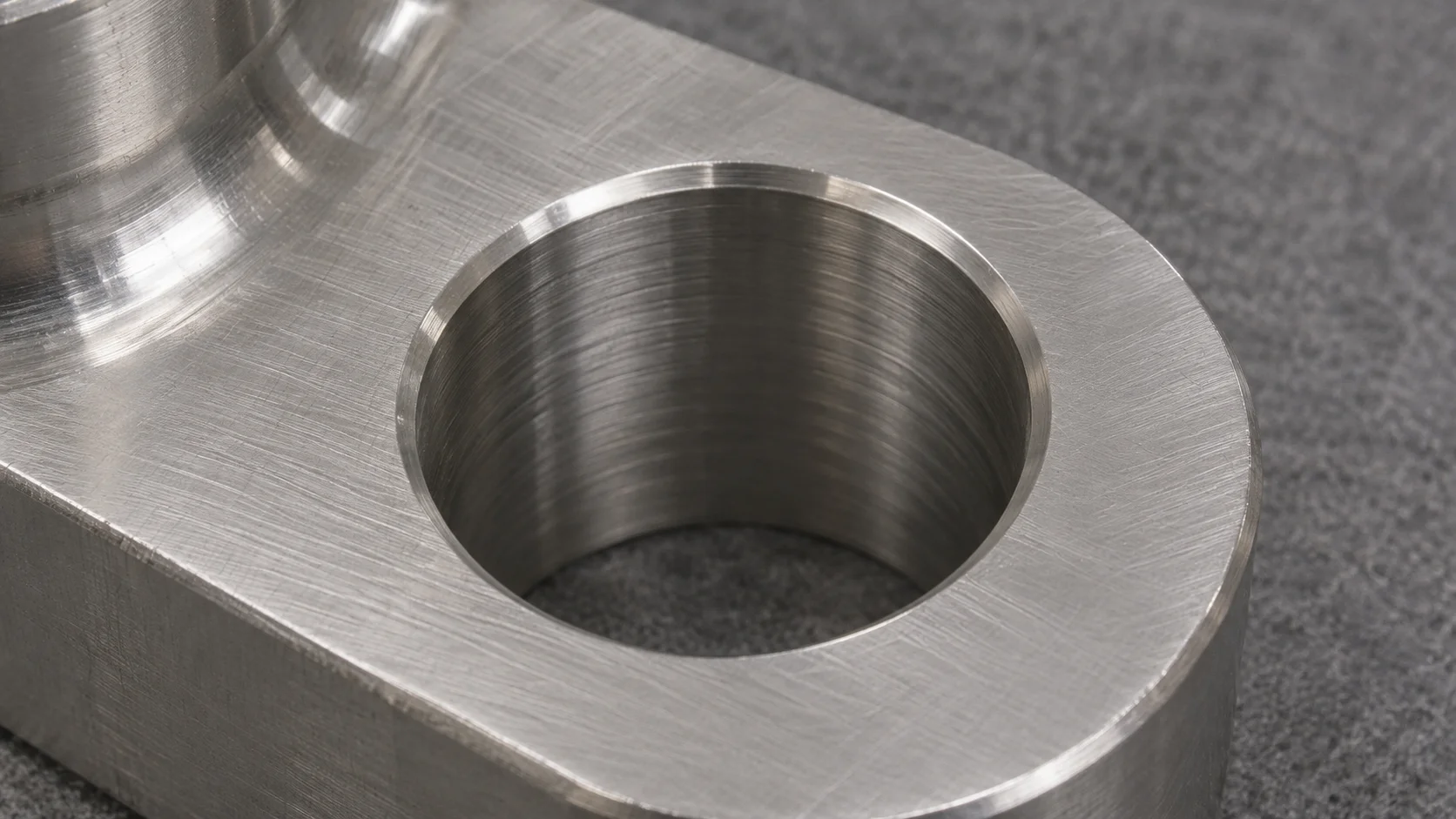
A part can appear to change size because of its temperature, support or inspection method. Material stress and manufacturing sequence can also affect the component itself. Establish comparable measurement conditions before choosing a cause.
Record whether the part was measured while clamped or supported in another condition. For a flexible flange, the way it is restrained can affect the observed result. Follow the drawing's specified condition and discuss any interpretation that affects acceptance.
Compare the drawing references, instruments and inspected features. A bore diameter check and an evaluation of its location relative to a mounting face answer different questions. Inspection alignment should represent the relationships being evaluated.
Also identify the processing stage. A result taken before heat treatment or finishing belongs to that stage. Determine which characteristics need verification on the completed part and keep the corresponding records linked to the delivery.
For disagreements near a limit, ask the quality teams to review the measurement method and uncertainty. Resolve the comparison with documented conditions and traceable results.
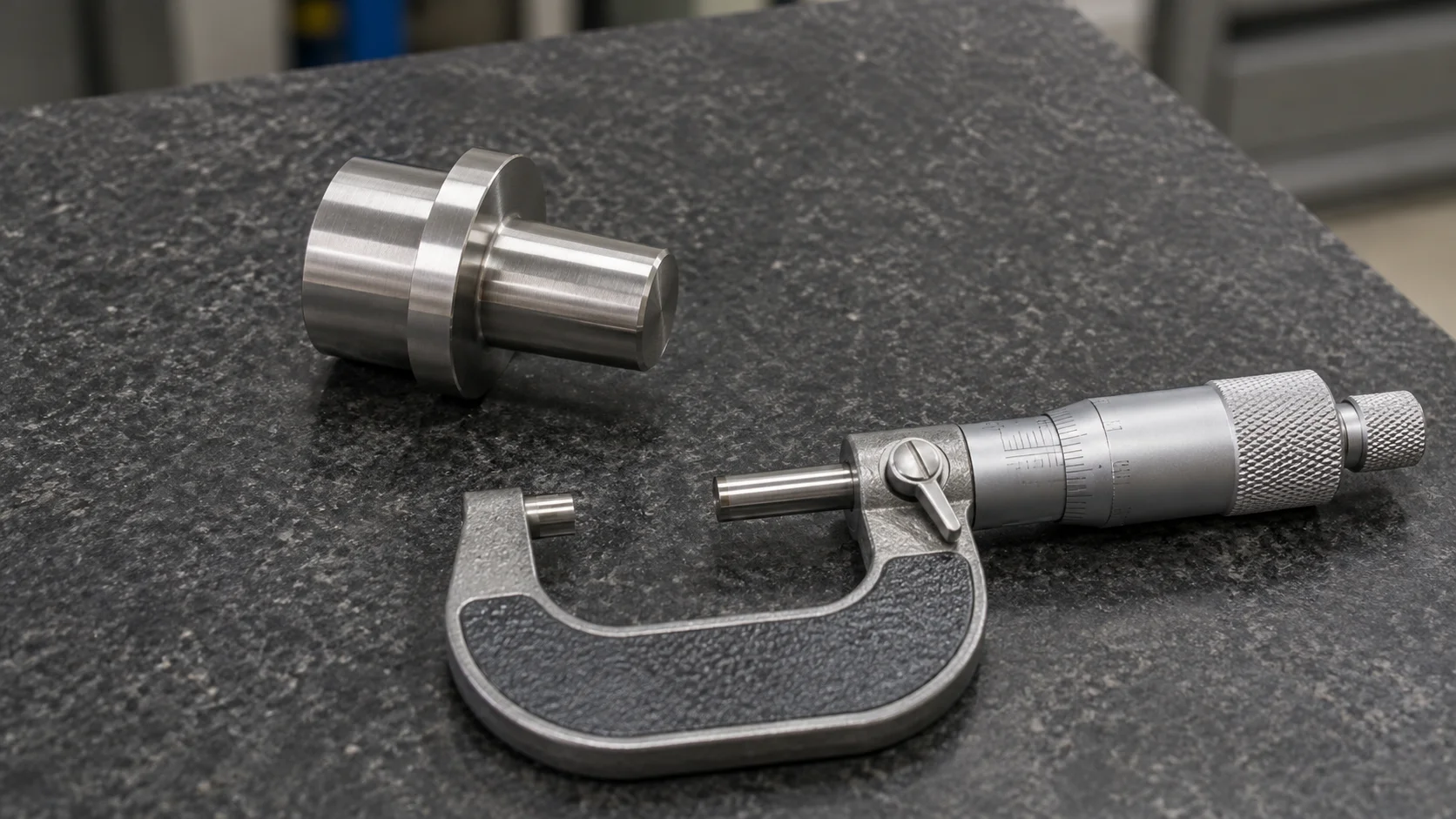
Surface condition depends on more than the final cutting pass. Chips, handling fixtures, cleaning, storage and contact between parts can affect the delivered component.
Rust-colored marks require a review of material identity and exposure as well as surface contamination. Iron contamination can arise from contact with unsuitable tools, particles or handling equipment. The investigation should establish the history of the affected surface.
Discuss the required cleaning and treatment with the supplier. If the order specifies passivation or another surface process, identify the applicable requirement and evidence. The suitability of that treatment depends on the actual grade, surface condition and application.
Preserve texture, appearance and dimensions as separate acceptance items. A polished surface may meet an appearance reference while a functional interface still requires dimensional or texture verification.
BIE includes cleaning and appropriate surface protection in its stated approach to surface-quality control. Specify the intended delivered condition so cleaning, finishing and handling can be discussed for the actual application.
BIE's surface finishing information provides a starting point for a project discussion. Agree the actual finish, inspection and protection requirements for the component being quoted.
Consider an illustrative stainless steel housing with a locating bore, mounting flange and threaded cross-hole. Receiving inspection finds burrs at the cross-hole and a rough area inside the bore. Assembly also reports that the flange does not seat consistently.
Begin by identifying the affected parts and drawing revision. Record each concern separately. The burr, bore surface and seating issue may involve different operations or inspection conditions.
For the cross-hole, review the edge requirement and internal access. For the bore, examine its surface requirement and the manufacturing evidence. For the flange, compare support, cleanliness and measurement conditions with the assembly arrangement.
Ask the supplier to propose corrections tied to these findings. Specify what needs to be rechecked, including any feature that could be affected by rework. Retain records of the accepted disposition and verification.
This is a hypothetical investigation example. Its purpose is to show how several observations can be organized into reviewable questions. The actual component determines the evidence and actions required.
Containment identifies and separates work that may be affected. Ask how the supplier will establish the relevant production interval, tool change, setup or material lot. Keep that identification connected to the inspected parts.
Next, agree the disposition. Rework, replacement and acceptance of a deviation require the appropriate authorization. Record the specific feature, quantity and condition covered by the decision.
A corrective action should explain the evidence for the cause and the proposed change. Its verification needs to address the original failure and any associated requirements. Keep the approved process and inspection revisions available for repeat orders.
For an overseas delivery, coordinate this decision with shipment release. Purchasing and receiving teams should know whether the goods include reworked parts, replacement parts or an approved exception.
A short, organized record makes the investigation easier to continue between engineering, purchasing and the manufacturing team. Use one current drawing and identify the evidence against it.
| Information | What to include |
| Product definition | Part number, drawing revision, material grade and condition |
| Observation | Affected feature, clear photographs and how the concern was found |
| Inspection evidence | Requirement, measured result, method and processing condition |
| Scope | Affected quantity and part or lot identification |
| Proposed action | Correction, approval needed and verification scope |
| Delivery decision | Release status and required accompanying records |
Provide the application context that changes the decision. Identify sealing, locating, sliding and visible surfaces. Explain any cleaning environment or assembly condition that the supplier needs to consider.
If an apparent defect is acceptable under the agreed specification, record the basis for that conclusion. If the specification leaves a functional concern unanswered, resolve it through an approved clarification or revision.
BIE provides CNC machining services, including milling and turning. Its company profile also describes surface-treatment and assembly services, allowing these requirements to be discussed alongside the machined component.
For initial project screening, BIE's capability information lists milling dimensions up to 1200 × 850 × 600 mm and turning dimensions up to 700 mm in diameter and 1000 mm in length. These are screening references. Geometry, material, workholding, access and inspection need review for the specific part.
Send the drawing and model with the grade, condition, quantities and finish requirements. Highlight the critical interfaces and required reports. For an existing quality concern, include the observation and records listed above so the discussion starts with the relevant evidence.
Possible contributors include material adhesion, tool condition, vibration and chip contact. Identify the affected operation and inspect the evidence before choosing a correction. Compare the result against the actual surface and functional requirements.
Work hardening describes a material response to deformation. Determine whether the resulting condition affects the specified requirements. The investigation needs material, process and inspection evidence for the component.
The appropriate change depends on the mechanism involved. Review the tool, engagement, material and setup together. A speed change alone may leave the cause unresolved or change another aspect of cutting behavior.
Identify the relevant edges and the intended finished condition. Call out functional chamfers or protected interfaces separately. Agree how difficult internal locations will be checked after processing.
Review surface contamination, exposure conditions and material suitability. Retain the material and handling history. The appearance of a mark alone provides insufficient evidence for a complete diagnosis.
Agree the material documents, dimensional records and finishing evidence needed for the application. Link them to the drawing revision and supplied parts or lot. Confirm the report scope before production.
Stainless steel machining quality improves when the material, manufacturing route and inspection requirements are considered together. Record the symptom, investigate the relevant mechanisms and verify each correction against the component's function and drawing.
Copyright © Dongguan BIE Hardware Co., Ltd - Privacy policy